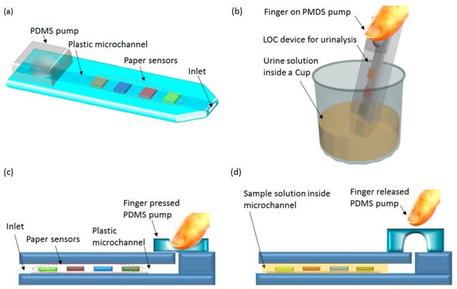
Fig. 1 (a) Conceptual scheme of a hybrid lab-on-a-chip (LOC) device made of patterned
polycarbonate (PC) sheet for urinalysis, (b) urine solution inside a cup, and (c and d) its operational steps.
(c) Finger force is applied to initiate negative pressure to move sample solution into the LOC device chamber, and
(d) the solution flows into the device chamber to react with the reagent pads.
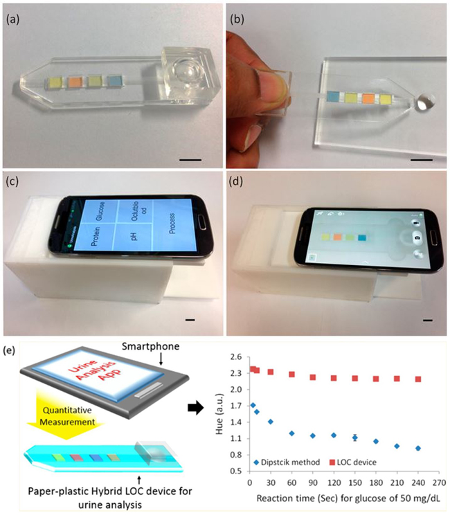
Fig. 2 (a) Fabricated hybrid LOC device with PDMS micropump,
(b) insertion of urine analyte into the reagent chambers of the LOC device by the elastic
restoration force of a PDMS micropump, (c) a smartphone on the top of a white acrylic imaging box,
(d) the disposable hybrid LOC device inside the acrylic box for imaging. The scale bars equal 1 cm, and
(e) Comparative syudy on proposed and conventional method.
- Uddin M. Jalal et al., Anal. Chem. 2017, 89, 13160−13166
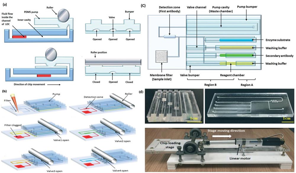
Fig. 3 (a,b) Working mechanism of the PDMS micro-pump, (c) Conceptual schematic of PDMS micro-pump,
and (c) The developed device.
- Uddin M. Jalal et al., Lab Chip, 2018, 18, 1310–1319.
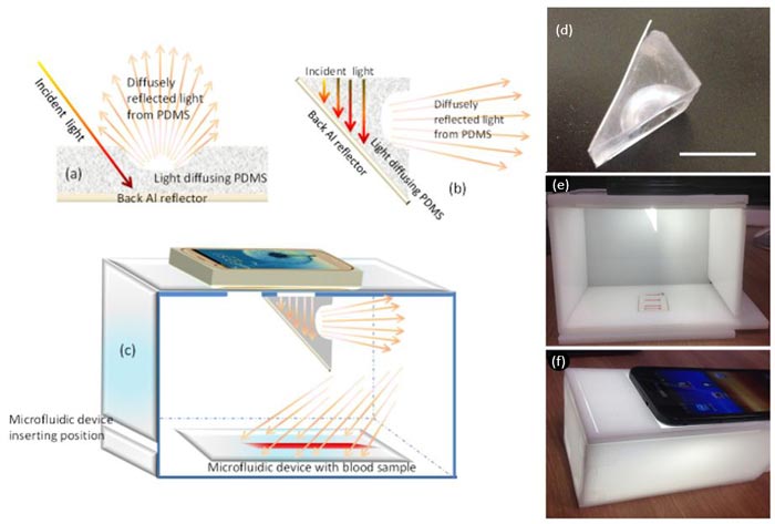
Fig. 4 (a) Light diffusing effect from a U-shaped PDMS placed on a reflecting aluminum (Al)
back contact, (b) PDMS diffuser used in our optical model on the reflecting
aluminum (Al) back contact, (c) Schematic side view of light diffusion effect from a PDMS media on the disposable
microfluidic device. (d) PDMS light diffuser (1 cm scale bar), (e) side view of white acrylic imaging
box with disposable microfluidic device with light flashing, and (f) image of the photographing moment
turning on a flashlight of the smartphone.
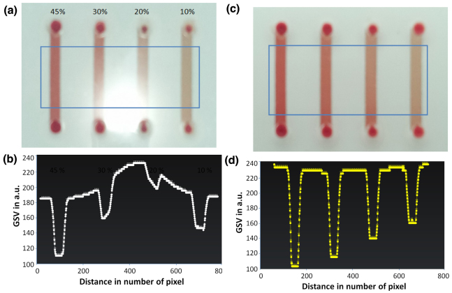
Fig. 5 Images of different hematocrit samples (a) without, and (c) with PDMS light
diffuser with corresponding gray scale value (GSV) shown in (b), and (d) respectively.
- Uddin M. Jalal et al., Sensors and Actuators B 239 (2017) 52–59
20 Kwangwoon-ro, Nowon-gu, Seoul 01897, Korea | +82-(0)2-940-5114